HEIC to JPG Converter Download for Windows 11, 10
HEIC to JPG Converter Download for Windows 10, 11 is an easy-to-use tool to convert HEIC and HEIF photos from your iOS device into JPG and other popular image formats.
Download for Free
HEIC to JPG Converter Download for Windows 10, 11 is an easy-to-use tool to convert HEIC and HEIF photos from your iOS device into JPG and other popular image formats.
Download for FreeThe iPhone and other new IOS devices store photos in HEIC format because it uses less memory space. This is beneficial because many photo formats can really eat up your disk space. In fact, this new format allows high quality photos to be stored in smaller file sizes. For people who take a lot of pictures, this is a huge benefit.
People often take many pictures on their iPhones, and now this will not eat up the disk space. It is easy to convert HEIC to JPG Windows 11 with this simple software; it is only a matter of importing the photos and making a few clicks of the mouse.
JPG format has been around for years, and it is very compatible for sharing and uploading. It actually supports all operating systems, including Mac, Android, IOS, Windows, and UNIX. HEIC only supports IOS 11+ and MacOS High Sierra. Therefore, you need HEIC to JPG software to convert HEIC images to view them on the Windows or Android platforms.
Download for Free The new iPhones save photos in High Efficiency Image Coding (HEIC) format because it uses much less storage space. However, many applications may not support this format. When you use HEIC to JPG converter software, you can easily convert your photos so that you can view them and share them across all of your devices.
Once you convert your photos, you can upload them, share them, or publish them in the JPG format.
The HEIC to JPG Converter software has a number of great features that allow you to quickly convert your photos to JPG or PNG. You can use Batch Mode to convert a number of pictures at the same time, and you can add watermarks, logos, or text to as many as you would like very easily. This program offers automatic level adjustment and color optimization, so your photos will look fantastic when you are done.
Download for Free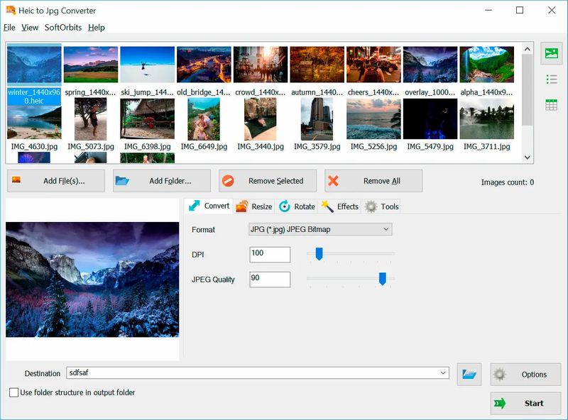
We'd like to alert you if you choose to use Windows's automatic transfer mode and convert HEIC files to JPEG. When you connect your iPhone or iPad to a Windows PC, the files are automatically converted to JPEG format. It's important to know that this mode doesn't always work as it should. In our tests, some of the photos were transferred in low quality or even corrupted. So, while this method is free, we don't recommend using it unless you're willing to risk losing your photos. If you want a reliable and easy-to-use solution, we recommend using SoftOrbits HEIC to JPEG Converter program with a lot of customizable options.
In addition, you can rename an entire batch of photos at the same time, saving you time when you are editing. You can change the canvas size and flip, mirror, or rotate the photos as well after you drag and drop them onto the screen. The HEIC to JPG software is packed with great features that will make converting and editing your photos very easy. The HEIC to JPG software boasts a fast conversion speed, allowing you to convert large batch of photos in no time.
You can use this program with Windows PCs and laptops, and your pictures will quickly be converted from HEIC to JPG so that you will be able to publish them or share them to your social media account. You may want to store your photos in the HEIC format since it uses less storage space, and then use the program to convert them when you need to share.
When you perform the HEIC to JPG converter download, install and open it, you will see your pictures across the top. You can add more photos by clicking Add files. If you have a batch of photos, you can add them in a folder if you wish.
The program does more than convert files; you can resize your photo or use the effects or tools to edit it.
When you are ready, you can choose the destination folder and click on Start. In no time, the HEIC to JPG software will convert your photos to the JPG format. Now you can share your photos on social media or publish them on your website.
There are a number of other differences between the two image file formats. HEIC is a standard format that was developed by the MPEG group as a successor to the widely used JPEG format. HEIC uses a 16-bit deep color, whereas JPG uses 8-bit. As a result, there is a wider range of colors on the HEIC file. In addition, you can make changes to the HEIC file more easily, including the front, middle, and background of the photo. HEIC image format is great for editing.
HEIC format gives you the best of both worlds because you will have a superior quality photo that can be compressed to a smaller file, but it can easily be converted to the universal JPG with a converter when you want to share it.
If you have the iPhone 8+, you will need to find HEIC to JPG converter download to view your photos on your Windows operaing system. HEIC to JPG Converter Software has a simple interface that makes it a user-friendly program that quickly converts your photos for you. All you need to do is download and open the software, and your photos should appear across the top of the screen.
Not only can you convert your photos, but you can resize them, flip them, mirror them, or rotate them. There are different effects and tools available, and you can make edits with one click. You can share your photos and then convert them back to HEIC so that they won’t take up as much disk space.
In addition, you can add text, a logo, or a watermark to your photos in a few simple steps. If you have a group of photos to edit at once, you can use Batch Mode to take care of it quickly.
The HEIC format makes it possible to take even more photos and store them on your PC or laptop. The HEIC to JPG Converter software makes it easy for you to edit and convert your photos to store them and share them online.
Download for Free


Comments (0)